Beat Breather Stereo

Detailed: LSP Beat Breather Stereo (BB1S)
Formats: CLAP, JACK, LADSPA, LV2, VST2, VST3
Categories: Dynamics
Developer: Vladimir Sadovnikov
Description:
This plugin allows to drive much more dynamics into punchy sounds like drums and make them breathe again.
The plugin detects punchy sounds and adds more dynamics to them. This is acieved by applying multi-stage processing:
- Frequency split - at this stage the whole frequency range becomes split into individual bands. To make sound much cleaner, the linear phase crossover is applied which adds some latency but provides several benefits:
- Unlike classic crossovers which use IIR (Infinite Impulse Response) filters to split signal into multiple bands and shift the phase of the audio signal at band split points, the Linear Phase allows to use FIR (Finite Impulse Response) filters which are deprived of this.
- Unlike most IIR filters which are designed using bilinear transform, linear phase filters allow simulate their transfer function to look like the transfer function of analog filters, without deforming it's magnitude envelope near the nyquist frequency.
- Unlike design of classic Linkwitz-Riley filters, the design of IIR filters provides shorter transition zone of the filter.
- Unlike classic IIR filters the slope of the FIR filter is not restricted to be the multiple of 6 dB.
- Punch detection - detection of peaks above the average level of the audio. For that case two type of RMS values are computed:
- Long time - the long-time RMS value (by default, the esitmation period is 400 ms) to estimate the average level of the audio signal.
- Short time - the short-time RMS value (by default, the estimation period is less than 20 ms and depends on the frequency range) to estimate the envelope of the changing in time signal.
- Punch filtering - additional stage to eliminate some noise from the signal not associated with punches.
- Beat processing - short-time dynamic amplification of the frequency band according to the signal passed from the punch filter.
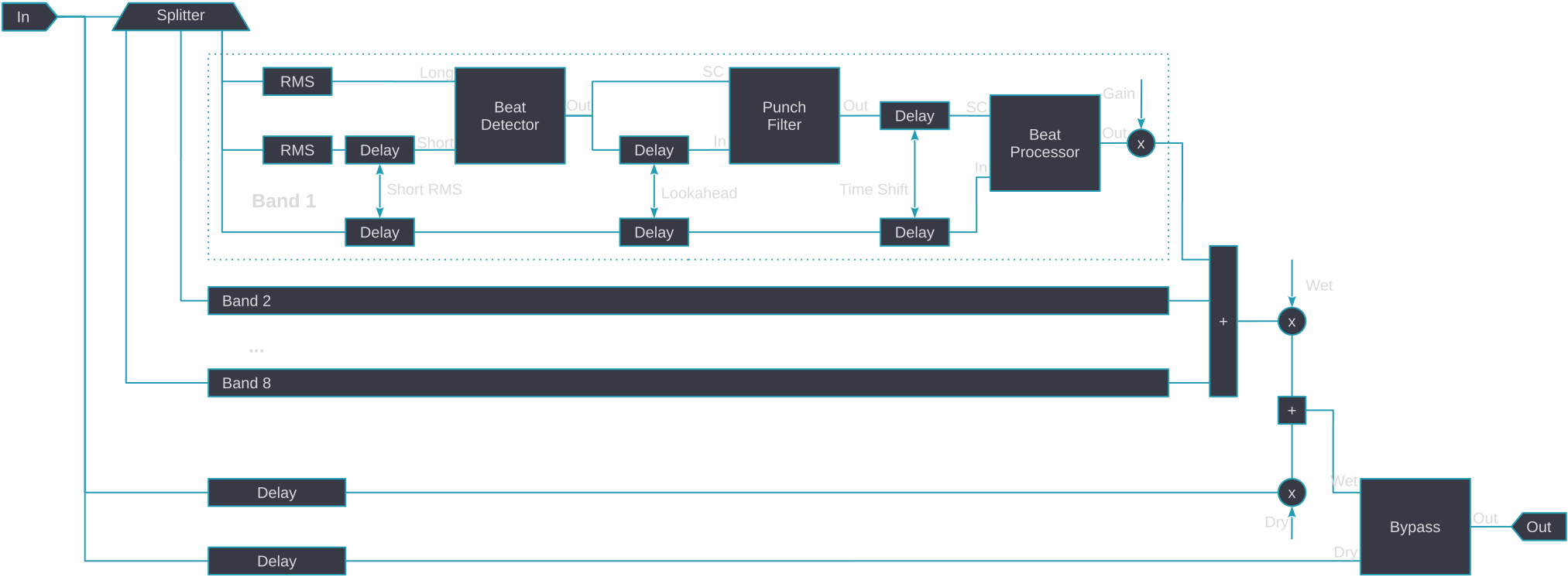
The simplified schema of the device is shown on the figure below.

Controls:
- Bypass - bypass switch, when turned on (led indicator is shining), the output signal is similar to input signal but delayed by the latency introduced by the plugin.
- Stereo Split - enables independent compression of left and right channels.
- Filters L, R - enables drawing transfer function of each sidechain filter on the spectrum graph.
- Zoom - zoom fader, allows to adjust zoom on the frequency chart.
'Analysis' section:
- FFT L, R In - enables FFT curve graph of input signal on the spectrum graph.
- FFT L, R Out - enables FFT curve graph of output signal on the spectrum graph.
- Reactivity - the reactivity (smoothness) of the spectral analysis.
- Shift - allows to adjust the overall gain of the analysis.
'Signal' section:
- Input - the amount of gain applied to the input signal before processing.
- Output - the amount of gain applied to the output signal before processing.
- Dry - the amount of dry (unprocessed) signal passed to the output.
- Wet - the amount of wet (processed) signal passed to the output.
- Dry/Wet - the balance between the mixed signal (see Dry and Wet knobs) and unprocessed (Dry) signal.
- In - the input signal meter.
- Out - the output signal meter.
Common tab controls:
- Band - the button that enables the corresponding band. Band #1 is always enabled and can not be disabled.
- S - turn on the soloing mode of the corresponding band.
- M - mute the corresponding band.
- Chain output - output the signal from the selected chain:
- BF - output the signal directly from Band Filter.
- PD - output the signal directly from Punch Detector.
- PF - output the signal directly from Punch Filter.
- BP - output the signal directly from Beat Processor (default).
'Band filter' tab:
- Range - shows the frequency range of the corresponding band and allows to tune the split frequency.
- Input - the level meter of the input signal for the corresponding band.
- Output - the level meter of the output signal from the corresponding band.
- HPF - the slope of the hi-pass filter for the corresponding band.
- LPF - the slope of the lo-pass filter for the corresponding band.
- Flatten - the additional flattening of the band by cutting the high cap of the band.
- Gain - the output gain of the band.
'Punch Detector' tab:
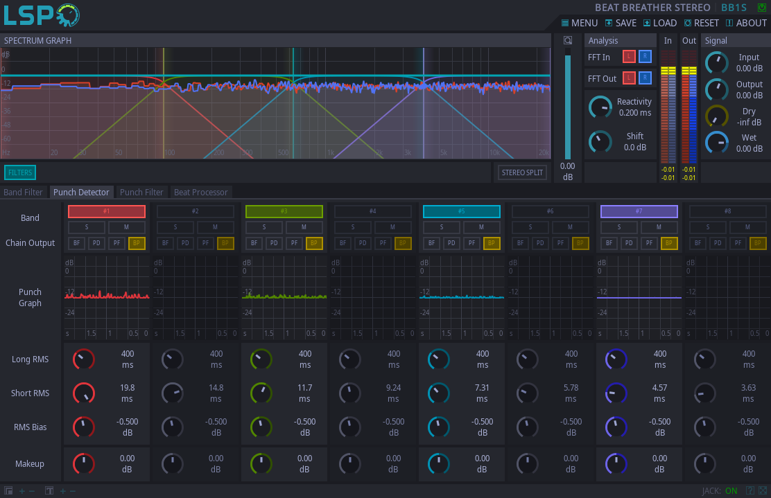
- Punch Graph - the graph which shows detected punches for the corresponding frequency band.
- Long RMS - the time frame for estimating long-time RMS value.
- Short RMS - the time frame for estimating short-time RMS value.
- RMS Bias - additional amplification of short RMS value for effective noise removal.
- Makeup - the makeup gain of the signal passed from the Punch Detector to the Punch Filter.
'Punch Filter' tab:
- Reduction Graph - the graph that demonstrates the work of the Punch Filter for the corresponding band.
- Lookahead - additional lookahead for the Punch Filter.
- Attack - the attack time of the Punch Filter.
- Release - the release time of the Punch Filter.
- Threshold - the threshold below which the input signal becomes gain-reduced.
- Zone - the size of the transition zone between fully gain-reduced signal and non-reduced signal.
- Reduction - the maximum gain reduction of the signal.
'Beat Processor' tab:
- Gain Graph - the graph that demonstrates the work of the Beat Processor for the corresponding band.
- Time Shift - the time shift of the gain amplification impulse relatively to the original signal. If positive, the amplification happens some time after the punch, some time before the punch if negative.
- Attack - the attack time of the Beat Processor.
- Release - the release time of the Beat Processor.
- Threshold - the threshold above which the signal becomes amplified.
- Ratio - the amplification ratio of the original signal.
- Max Gain - the maximum amplification gain that can be applied to the original signal.


