Multiband Clipper Mono

Detailed: LSP Multiband Clipper Mono (MBCL1M)
Formats: CLAP, JACK, LADSPA, LV2, VST2, VST3
Categories: Dynamics
Developer: Vladimir Sadovnikov
Description:
This plugin allows to drive much more loudness by cutting extra peaks and reach extreme loudness levels at the output. The key features are following.
Classic and Linear Phase crossover modes allow to bring more flexibility to the mastering process. Low-pass and High-pass pre-filters allow to cut unnecessary frequencies before processing. Dithering allows to add some dithering noise to the signal and make the final mix more detailed. Loudness limiting option allows to control the input loudness, per-band loudness and input loudness at the output clipper. Overdrive protection allows to add short-time compression to the signal to make clipping effect less noticeable. Multiple sigmoid functions allow to select the best sounding clipping function. Input and output loudness measurments allow to control loudness level of the signal in LUFS.
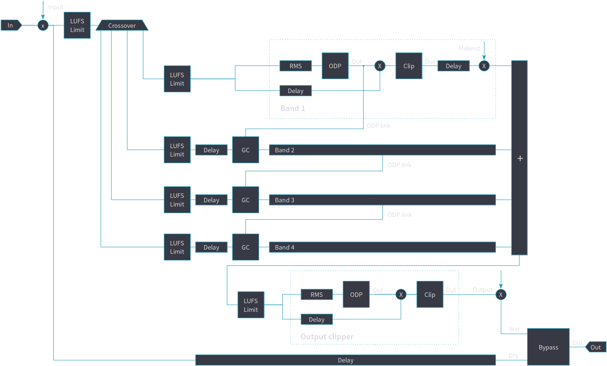
The simplified schema of the device is shown on the figure below.

Controls:
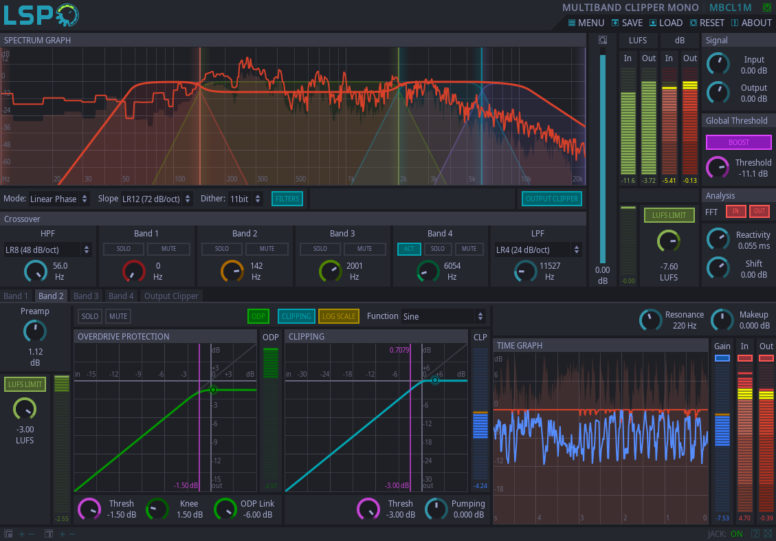
- Bypass - bypass switch, when turned on (led indicator is shining), the output signal is similar to input signal. That does not mean that the plugin is not working.
- Mode - crossover mode:
- Classic - classic Linkwitz-Riley filters are used for splitting signal into multiple frequency bands.
- Linear Phase - FFT transform is used to split audio signal into multiple bands, introduces additional latency.
- Slope - the slope of crossover filters:
- LR4 (24 dB/oct).
- LR8 (48 dB/oct).
- LR12 (72 dB/oct).
- LR16 (96 dB/oct).
- Dither - allows to enable dithering noise depending on the bitness of the desired output signal.
- Filters - the button that enables drawing of crossover filter characteristics.
- Output clipper - enables output clipper.
- LUFS Limit button enables limiting of LUFS value at the input of the plugin
- LUFS Limit knob allows to set maximum LUFS value of the input signal.
Signal section:
- Input - additional gain applied to the input signal.
- Output - additional gain applied to the output signal.
Global Threshold section:
- Boost - allows to additionally boost the processed signal to compensate threshold level lower than 0 dB.
- Threshold - allows to adjust lower than 0 dB clipping threshold.
Analysis section:
- Reactivity - the reactivity (smoothness) of the spectral analysis.
- Shift - allows to adjust the overall gain of the analysis.
- FFT In - enables FFT curve graph of input signal on the spectrum graph.
- FFT Out - enables FFT curve graph of output signal on the spectrum graph.
- Filters - enables drawing transfer function of each sidechain filter on the spectrum graph.
- Surge - enables surge protection mechanism.
Meters:
- LUFS - input and output loudness meters.
- dB In - the level meter of the input signal.
- dB Out - the level meter of the output signal.
- LUFS Limit - the amount of gain reduction applied to the input signal while limiting the loudness.
Crossover section:
- HPF combo allows to select the slope of high-pass pre-filter of the input signal.
- HPF knob allows to adjust the cut-off frequency of the high-pass filter.
- Band solo - allows to solo specific band.
- Band mute - allows to mute specific band.
- Band knob - allows to set the split frequency between bands.
- Band 4 act - enables additional fourth band for processing.
- LPF combo allows to select the slope of low-pass pre-filter of the input signal.
- LPF knob allows to adjust the cut-off frequency of the low-pass filter.
Band tabs:
- Preamp - allows to control input gain level of the specific band.
- LUFS Limit button - allows to enable loudness limiting for the specific band.
- LUFS Limit knob - allows to set maximum allowed loudness of the signal at the input of the band.
- LUFS Limit meter - the amount of gain reduction applied to the input signal of the band while reducing loudness.
- Act - enables additional fourth band.
- Solo - enables solo mode for the selected band.
- Mute - mutes the selected band.
- ODP - enabled overdrive protection compressor.
- Clipping - enables clipping function applied to the signal.
- DC Compensate - enables compensation of the DC offset applied at the clipping stage.
- Log Scale - switches clipping function graph representation in linear/logarithmic scale.
- Function - clipping function
- ODP Thresh - the threshold of the overdrive protection compressor.
- ODP Knee - the knee of the overdrive protection compressor.
- ODP Meter - the amount of gain reduction applied to the signal while compressing it's peaks.
- ODP Link - knob that controls the side-chaining of the current band by the previous one.
- Clip Thresh - the threshold of the clipping function. Signals below the threshold have constant amplification.
- Clip DC offset - the additional DC offset applied to the signal before clipping stage.
- Clip Pumping - additional way to pump the loudness of the band by applying extra amplification and keeping peaks not greater than 0 dB.
- Clip Meter - the amount of gain reduction applied at the clipping stage.
- Resonance - sets up ODP compression time by selecting the dominating frequency in the signal.
- Makeup - the output gain of the band
- Time Graph Gain - the overall band gain reduction meter.
- Time Graph In - the input signal meter of the band.
- Time Graph Out - the output signal meter of the band.
Output Clipper tab:
- LUFS Limit button - allows to enable loudness limiting at the input of the output clipper.
- LUFS Limit knob - allows to set maximum allowed loudness at the input of the output clipper.
- LUFS Limit meter - the amount of gain reduction applied to the input of the output clipper signal while reducing loudness.
- Active - enables output clipper.
- ODP - enabled overdrive protection compressor.
- Clipping - enables clipping function applied to the signal.
- DC Compensate - enables compensation of the DC offset applied at the clipping stage.
- Log Scale - switches clipping function graph representation in linear/logarithmic scale.
- Function - clipping function
- ODP Thresh - the threshold of the overdrive protection compressor.
- ODP Knee - the knee of the overdrive protection compressor.
- ODP Meter - the amount of gain reduction applied to the signal while compressing it's peaks.
- Clip Thresh - the threshold of the clipping function. Signals below the threshold have constant amplification.
- Clip DC offset - the additional DC offset applied to the signal before clipping stage.
- Clip Pumping - additional way to pump the loudness of the band by applying extra amplification and keeping peaks not greater than 0 dB.
- Clip Meter - the amount of gain reduction applied at the clipping stage.
- Reactivity - sets up the reactivity of the ODP compressor.
- Time Graph Gain - the overall band gain reduction meter.
- Time Graph In - the input signal meter of the band.
- Time Graph Out - the output signal meter of the band.


