Oscilloscope x1

Detailed: LSP Oscilloscope x1 (O1)
Formats: CLAP, JACK, LADSPA, LV2, VST2, VST3
Categories: Utility
Developer: Stefano Tronci
Description:
This plugin implements a simple, but flexible, oscilloscope.
The oscilloscope channel has the following features:
- X input channel.
- X output channel.
- Y input channel.
- Y output channel.
- EXT input channel.
- Triggered operation.
- XY operation.
- Goniometer operation.
The X channel is used to drive the horizontal coordinate of the trace plotted on the oscilloscope graph in XY and Goniometer operation. In Triggered mode the horizontal coordinate is driven by an internal sweep generator.
The Y channel is used to drive the vertical coordinate of the trace plotted on the oscilloscope graph.
The EXT (external) channel is an alternative channel that can be used to drive the trigger.
All channels can be freely oversampled and passed through a DC blocking filter.
In a more general fashion with respect most scopes, each channel has a full set of channels and can have a different timebase. Multichannel scopes also have general controls that can be used to override multiple channels.
Controls:
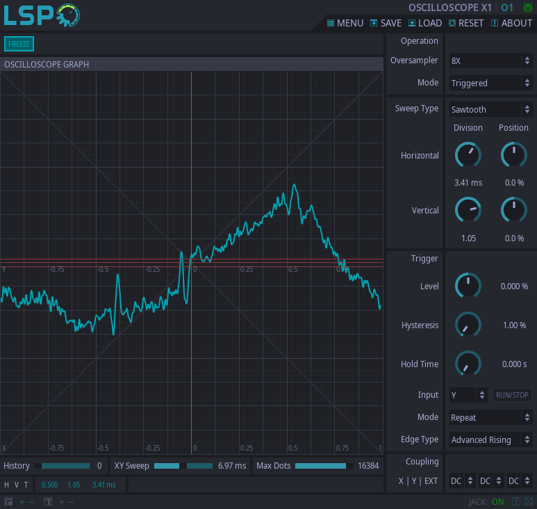
'OSCILLOSCOPE GRAPH' section:
The Oscilloscope Graph and the controls above and below it are documented below.
- OSCILLOSCOPE GRAPH - This graph will show the various traces the oscilloscope is able to produce. The graticule shows bright lines and faint lines. The Divisions, both vertical and horizontal, are shown as bright lines.
- Freeze Controls - These controls are available on the top left of the oscilloscope graph. Use these controls to freeze the entire scope graph (Freeze button) or single channels with the dedicated buttons (for multichannel versions).
- Mute/Solo Controls - These controls are available for multichannel scopes on the top right of the oscilloscope graph. They allow to set each individual channel to solo or mute.
- History - This control, located at the bottom of the oscilloscope graph, allows the user to set the amount of previous traces that are allowed to persist on the oscilloscope graph together with the current trace. Older traces are plotted with progressive transparency. For stable signals, the resulting effect is akin to that of the persistency of analog scopes.
- XY Sweep - This control, located at the bottom of the oscilloscope graph, is enabled only for XY and Goniometer modes. In these modes, it controls the amount of memory the oscilloscope uses to draw the traces.
- Max Dots - This control, located at the bottom of the oscilloscope graph, allows the user to tune the amount of dots that are used to draw the traces on the oscilloscope graph. The higher number of dots can produce smoother traces, but at the expenses of UI load.
- H|V|T Labels - These labels mirror the values of division chosen by the user on the main scopes settings - horizontal, vertical and time. They are located at the bottom of the oscilloscope graph for quick reference.
'Controls' section:
This section, located at the rigtmost side of the UI, contains the main oscilloscope controls.
- Channel Selector - For multichannel scopes, this control is located at the top right of the UI and is used to select the channel on which the controls below will operate.
- Freeze/Solo/Mute - These buttons are used to set the selected channel to Freeze, Solo end Mute respectively.
- Oversampler - This control is used to select the oversampler mode. High oversampling produces smoother traces. Available modes are below.
- None - oversampling is not used.
- x2 - 2x downsampling.
- x3 - 3x downsampling.
- x4 - 4x downsampling.
- x6 - 6x downsampling.
- x8 - 8x downsampling.
- Mode - This control sets the main oscilloscope mode. The following modes are available:
- XY - In this mode the the trace horizontal coordinate is driven by the channel X input, while the vertical trace coordinate is driven by the channel Y input.
- Triggered - In this mode the trace horizontal coordinate is driven by the internal sweep generator, which is in turn controlled by the channel trigger, while the trace vertical coordinate is driven by the channel Y input.
- Goniometer - In this mode the trace horizontal coordinate is driven by half of the sum of the X and Y inputs, the vertical trace coordinate is driven by half their difference.
- Sweep Type - This control is active in Triggered mode and sets the type of sweep signals which drives the trace X value. The sweeps are initiated when the trigger fires and, after completion, remain dormant until the next trigger fire is allowed. The following types are available.
- Sawtooth - The sweep is a sawtooth wave.
- Triangular - The sweep is a triangular wave.
- Sine - The sweep is a sine wave.
- Horizontal - These controls allow tuning of the horizontal trace properties. The available controls are listed below.
- Division - In Triggered mode, this control sets the size, in milliseconds, of the horizontal division value in the oscilloscope graph. In XY and Goniometer instead it controls, in units of amplitude, the horizontal division value in the oscilloscope graph.
- Position - This trigger allows to introduce an horizontal shift in the trace. The shift is specified as a percentage of the half horizontal span of the oscilloscope graph.
- Vertical - These controls allow tuning of the vertical trace properties. The available controls are listed below.
- Division - This control sets, in units of amplitude, the vertical division value in the oscilloscope graph.
- Position - This trigger allows to introduce a vertical shift in the trace. The shift is specified as a percentage of the half vertical span of the oscilloscope graph.
- Trigger - These controls tune the channel trigger. They are active only in Triggered mode.
- Level - This control sets the level of the trigger. The level is specified as a percentage of the half vertical span of oscilloscope graph. When the Edge Type is Simple, this level is shown in the oscillator graph as an horizontal line.
- Hysteresis - This control is active only for the Advanced Edge types. This control allows to split the trigger level in two levels, separated by the hysteresis value, that need to be crossed in the right order to cause the trigger to fire. The hysteresis value is specified as a percentage of the full vertical span of the oscilloscope graph. When the Edge Type is Advanced the values of level +/- hysteresis are shown on the oscilloscope graph as horizontal lines.
- Hold Time - This control sets, in seconds, the amount of time that needs to elapse between consecutive trigger firings. This time has a lower bound calculated internally from the sweep properties.
- Input - This control is used to select the input channel for the trigger. Available channels are Y and EXT.
- Run/Stop - This button is only active for Single and Manual modes and allows to start a trigger and sweep cycle.
- Mode - This control sets the trigger mode. The modes below are available.
- Single - In this mode, the scope is allowed to complete a single trigger and sweep cycle after which it freezes. To restart the cycle, use the Run/Stop button.
- Manual - In this mode the scope is allowed, after pressing the Run/Stop button, to complete a single trigger and sweep cycle after which it freezes.
- Edge Type - This controls set the trigger edge type. The following edge types are available
- None - In this edge type the trigger is firing with sweep period.
- Simple Rising - This edge type causes the trigger to fire when the signal passes through the threshold in the ascending direction. The threshold is set by the trigger Level control.
- Simple Falling - This edge type causes the trigger to fire when the signal passes through the threshold in the falling direction. The threshold is set by the trigger Level control.
- Advanced Rising - This edge type causes the trigger to fire when the signal passes through two thresholds in the ascending direction. The thresholds are set by the trigger Level and Hysteresis controls.
- Advanced Falling - This edge type causes the trigger to fire when the signal passes through two thresholds in the falling direction. The thresholds are set by the trigger Level and Hysteresis controls.
- Coupling X|Y|EXT - For each of the X, Y and EXT channels, these controls allow to set the coupling. The following couplings are available.
- AC - In this coupling type, the signal is passed through a DC block filter.
- DC - In this coupling type, the signal is unfiltered.
'Global Settings' section:
These controls are available only for multichannel scopes, and are located on the right of the oscilloscope graph. They are exactly the same of the 'Controls' section: and are used to override the single channels settings.
In order to override one channel control with the global, select the channel with the Channel Selector and activate the On button in the top of the Global Settings section.


